Display Properties -Color Tab
Power supply fan connector, J9H3
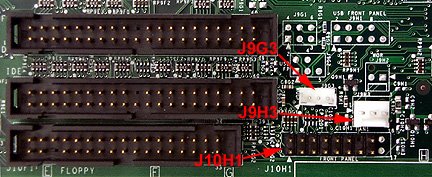
Gateway does not use this connector. However, it is populated on the board and available for use. The pinouts for J9H3 are:
| Pin | Signal name |
| 1 | Ground |
| 2 | +12 V (FAN_C) |
| 3 | Tach |
Front Panel Connector
The front panel connector is labeled J10H1 on the motherboard. Pin 1 is indicated by an arrow on the board (lower left pin in this graphic). Pin 2 is immediately above it. The pinouts for J10H1 are as follows:
| Pins | Signal Name |
|---|---|
| 1 and 3 | Hard disk activity LED |
| 2 and 4 | Power/Sleep/Message waiting light-emitting diode (LED) |
| 5 and 7 | Reset switch |
| 6 and 8 | Power switch |
| 9,11,13, and 15 | Infrared port |
| 10 and 12 | Sleep/Resume switch |
Power Connector
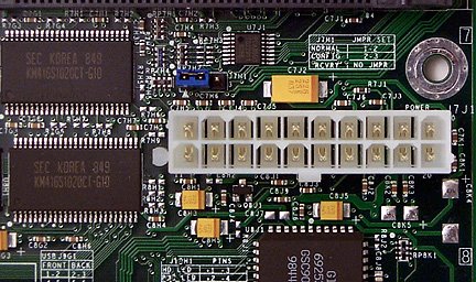
The motherboard can turn off the computer through software control. To enable soft-off control, Advanced Power Management (APM) must be enabled in the BIOS Setup Utility and in the operating system. When the computer basic input/output system (BIOS) receives the correct APM command from the operating system, the BIOS turns off power to the computer.
With soft-off enabled, the computer returns to the power state in which it was before power was interrupted.
The pinouts for J10H1 are:| Pin | Signal name |
| 1 | +3.3 V |
| 2 | +3.3 V |
| 3 | Ground |
| 4 | +5 V |
| 5 | Ground |
| 6 | +5 V |
| 7 | Ground |
| 8 | PWRGD (Power Good) |
| 9 | +5 VSB (Standby for real-time clock) |
| 10 | + 12V |
| 11 | +3.3 V |
| 12 | -12V |
| 13 | Ground |
| 14 | PS-ON# (power supply remote on/off) |
| 15 | Ground |
| 16 | Ground |
| 17 | Ground |
| 18 | -5 V |
| 19 | +5 V |
| 20 | +5 V |
這一篇是我有一張gateway主機板技術文件的資料鏈結存檔。
沒有留言:
張貼留言